PCB Testing
Home > PCB Testing
PCB Testing
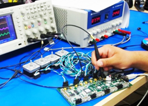
We also support in Board and product testing as per the customer specifications.
We offer services in Developing Test Software for complex PCBs using LabView, XJTAG (a tool for testing Boundary Scan Devices) Platform. We also develop In-circuit and Functional Test Programs for (Diagnosys) Schlumbergers’ S790 ATE.
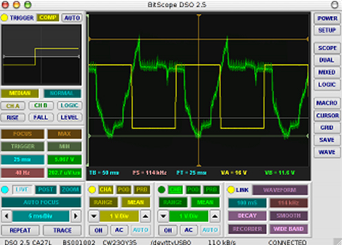
Functional Test
Functional test is used as a final manufacturing step. It provides a pass/fail determination on finished PCBs before they are shipped. A functional test’s purpose in manufacturing is to validate that product hardware is free of defects that could, otherwise, adversely affect the product’s correct functioning in a system application.
In short, functional test verifies a PCB’s functionality and its behavior. It is important to emphasize that the requirements of a functional test, its development, and procedures vary widely from PCB to PCB and system to system.
Functional testers typically interface to the PCB under test via its edge connector or a test-probe point. This testing simulates the final electrical environment in which the PCB will be used.
The most common form of functional test, known as “hot mock-up” simply verifies that the PCB is functioning properly. More sophisticated functional tests involve cycling the PCB through an exhaustive range of operational tests.
A functional test emulates or simulates a product’s operational environment to check its correct functionality. The environment consists of any device that communicates with the unit under test (UUT), for example, the UUT’s power supply or program loads necessary to make the UUT work properly.
The PCB is subjected to a sequence of signals and power supplies. Responses are monitored at specific points to ensure functionality is correct. The test is usually performed according to the OEM test engineer, who defines the specifications and test procedures. This test is best at detecting wrong component values, functional failures and parametric failures.
Test software, sometimes called firmware, allows production line operators to perform functional test in an automatic way through a computer. To do this, the software communicates with external programmable instruments as a digital multi-meter, I/O boards, and communication ports. The software combined with the fixture interfacing the instruments with the UUT make it possible to perform a FUNCTIONAL TEST.
Ready to discuss your requirement
we aimed to surpass the clients’ expectations by offering world class products and services.